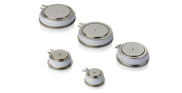
Home > Products Guide > Gate turn-off thyristor����� �������Ƴ������������ �������Ƴ������������ �������Ƴ������������ �������Ƴ������s (GTO)
Gate turn-off thyri����� �������Ƴ������������ �������Ƴ����������� �������Ƴ������������ �������Ƴ�������stors (GTO)
Production of����� �������Ƴ������������ �������Ƴ������������ �������Ƴ������� GTOs commenced in t����� �������Ƴ������������ �������Ƴ�������he mid 1980s. A GTO����� �������Ƴ������������ �������Ƴ������������ �������Ƴ����������� �������Ƴ������� is a thyristor th����� �������Ƴ������������ �������Ƴ������������ �������Ƴ������������ �������Ƴ�������at can be turned of����� �������Ƴ������������ �������Ƴ�������f by applying ����� �������Ƴ����������� �������Ƴ����������� �������Ƴ�������a current to t����� �������Ƴ������������ �������Ƴ�������he gate in the r����� �������Ƴ����������� �������Ƴ������������ �������Ƴ�������everse direction to tha����� �������Ƴ������������ �������Ƴ����������� �������Ƴ������������ �������Ƴ�������t required to tur����� �������Ƴ������������ �������Ƴ������������ �������Ƴ������������ �������Ƴ�������n it on.
GTOs are opti����� �������Ƴ����������� �������Ƴ������������ �������Ƴ������������ �������Ƴ�������mized for lo����� �������Ƴ������������ �������Ƴ������������ �������Ƴ������w conduction los����� �������Ƴ������������ �������Ƴ������������ �������Ƴ�������ses. The typical on����� �������Ƴ������������ �������Ƴ������������ �������Ƴ������������ �������Ƴ�������-off switching fr����� �������Ƴ������������ �������Ƴ�������equency is in the r����� �������Ƴ������������ �������Ƴ�������ange of 200 - 500 he����� �������Ƴ����������� �������Ƴ������������ �������Ƴ������������ �������Ƴ�������rtz for most applica����� �������Ƴ������������ �������Ƴ������������ �������Ƴ������������ �������Ƴ�������tions. GTOs are, by n����� �������Ƴ������������ �������Ƴ������������ �������Ƴ������������ �������Ƴ�������ature, relativ����� �������Ƴ������������ �������Ƴ������������ �������Ƴ�������ely slow switc����� �������Ƴ������������ �������Ƴ������������ �������Ƴ������������ �������Ƴ������hes.
Typical transition tim����� �������Ƴ������������ �������Ƴ����������� �������Ƴ������������ �������Ƴ�������es from on to of����� �������Ƴ������������ �������Ƴ����������� �������Ƴ������f state and vice vers����� �������Ƴ����������� �������Ƴ������������ �������Ƴ�������a are in a range of 10����� �������Ƴ������������ �������Ƴ������������ �������Ƴ������� - 30 microsec����� �������Ƴ����������� �������Ƴ������������ �������Ƴ������������ �������Ƴ�������onds. All GTOs requir����� �������Ƴ������������ �������Ƴ������e protective networks ca����� �������Ƴ����������� �������Ƴ������������ �������Ƴ������������ �������Ƴ�������lled "snubbers&quo����� �������Ƴ������������ �������Ƴ������������ �������Ƴ�������t; for turn-on and t����� �������Ƴ������������ �������Ƴ������urn-off. The����� �������Ƴ������������ �������Ƴ����������� �������Ƴ������������ �������Ƴ������� turn-on snubber circui����� �������Ƴ������������ �������Ƴ������������ �������Ƴ����������� �������Ƴ�������t, in essence a����� �������Ƴ������������ �������Ƴ�������n inductor, limi����� �������Ƴ������������ �������Ƴ����������� �������Ƴ�������ts the rate of cu����� �������Ƴ������������ �������Ƴ������rrent rise. For turn-of����� �������Ƴ������������ �������Ƴ�������f, the GTO r����� �������Ƴ������������ �������Ƴ������������ �������Ƴ�������equires a devi����� �������Ƴ������������ �������Ƴ�������ce that limits the����� �������Ƴ������������ �������Ƴ������� rate of voltage ri����� �������Ƴ����������� �������Ƴ������se, in essence a cap����� �������Ƴ������������ �������Ƴ�������acitor.
All ABB GTOs are����� �������Ƴ������������ �������Ƴ������� press-pack devices.����� �������Ƴ����������� �������Ƴ����������� �������Ƴ������ They are pressed w����� �������Ƴ������������ �������Ƴ�������ith a relativ����� �������Ƴ������������ �������Ƴ�������ely high force onto heat����� �������Ƴ������������ �������Ƴ������������ �������Ƴ������������ �������Ƴ�������-sinks which also serv����� �������Ƴ����������� �������Ƴ����������� �������Ƴ������������ �������Ƴ�������e as electrical����� �������Ƴ������������ �������Ƴ������������ �������Ƴ������������ �������Ƴ������� contacts to the p����� �������Ƴ������������ �������Ƴ������������ �������Ƴ������������ �������Ƴ�������ower terminals����� �������Ƴ������������ �������Ƴ������������ �������Ƴ������.
Asymmetric GT����� �������Ƴ������������ �������Ƴ������������ �������Ƴ������������ �������Ƴ�������Os are divid����� �������Ƴ������������ �������Ƴ������������ �������Ƴ�������ed in two categ����� �������Ƴ������������ �������Ƴ������������ �������Ƴ����������� �������Ƴ�������ories: Buffer layer a����� �������Ƴ����������� �������Ƴ����������� �������Ƴ����������� �������Ƴ�������nd Standard. Buff����� �������Ƴ������������ �������Ƴ������������ �������Ƴ������������ �������Ƴ�������er layer GTOs ����� �������Ƴ������������ �������Ƴ������have exceptionally l����� �������Ƴ������������ �������Ƴ����������� �������Ƴ������������ �������Ƴ�������ow on-state a����� �������Ƴ������������ �������Ƴ�������nd dynamic l����� �������Ƴ������������ �������Ƴ�������osses. Fine ����� �������Ƴ������������ �������Ƴ����������� �������Ƴ����������� �������Ƴ������pattern types (5SGF) are����� �������Ƴ������������ �������Ƴ������ optimised for f����� �������Ƴ����������� �������Ƴ�������ast switching and t����� �������Ƴ������������ �������Ƴ������������ �������Ƴ�������ransparent emitt����� �������Ƴ����������� �������Ƴ�������er (5SGT) for low on-sta����� �������Ƴ������������ �������Ƴ������������ �������Ƴ�������te losses.&nbs����� �������Ƴ������������ �������Ƴ�������p;The Standard GT����� �������Ƴ������������ �������Ƴ������������ �������Ƴ�������Os have excell����� �������Ƴ������������ �������Ƴ������ent trade-off be����� �������Ƴ������������ �������Ƴ������������ �������Ƴ������tween on-state and swi����� �������Ƴ������������ �������Ƴ������������ �������Ƴ������������ �������Ƴ�������tching losses.
| Part Number | VDRM (V) | VDC (V) | ITGQM @ ����� �������Ƴ������������ �������Ƴ������������ �������Ƴ������������ �������Ƴ������� Cs(A) | ITGQM @ ����� �������Ƴ������������ �������Ƴ������������ �������Ƴ������� Cs(µF) | Package* (mm) |
| Standard | |||||
| 5SGA 15F2502 | 2500 | 1400 | 1500 | 3 | 75/47 |
| 5SGA 20H2501 | 2500 | 1400 | 2000 | 4 | 93/63 |
| 5SGA 25H2501 | 2500 | 1400 | 2500 | 6 | 93/63 |
| 5SGA 30J2501 | 2500 | 1400 | 3000 | 5 | 108/75 |
| 5SGA 06D4502 | 4500 | 2800 | 600 | 1 | 58/34 |
| 5SGA 20H4502 | 4500 | 2200 | 2000 | 4 | 93/63 |
| 5SGA 30J4502 | 4500 | 2800 | 3000 | 6 | 108/75 |
| 5SGA 40L4501 | 4500 | 2800 | 4000 | 6 | 120/85 |
*Note: Pole-piece diam����� �������Ƴ������������ �������Ƴ�������eter / Housing height
| Part Number | VDRM (V) | VDC (V) | ITGQM @ Cs (A) | ITGQM @ Cs(µF) | Package* (mm) |
| Buffer layer | |||||
| 5SGF 30J4502 | 4500 | 3000 | 3000 | 3 | 108/75 |
| 5SGF 40L4502 | 4500 | 2800 | 4000 | 6 | 120/85 |
*Note: Pole-piece diam����� �������Ƴ������������ �������Ƴ������������ �������Ƴ�������eter / Housing he����� �������Ƴ������������ �������Ƴ������������ �������Ƴ�������ight

